
TE-WB (v1.5) | Oz DIY-WB | TE-5301 | 5301 kit | Older 5300 | Original FMD
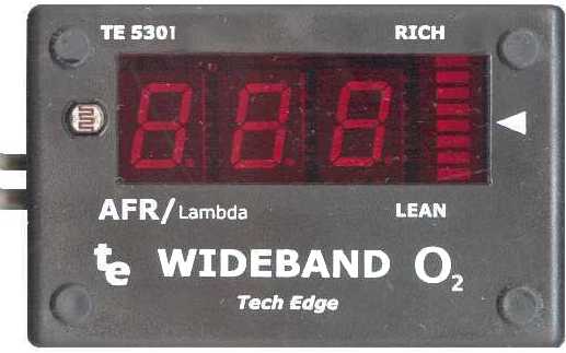 |
The TE-5301 is a 3 digit display calibrated to show AFR (or Lambda) as measured by the Oz DIY-WB or the TE-WB 1.5. The TE-5301 features :
|
The LDR sensor used for auto night dimming is shown on the left side of the face. The arrow on the right side of the face indicates the stoic region on the bar graph.
|
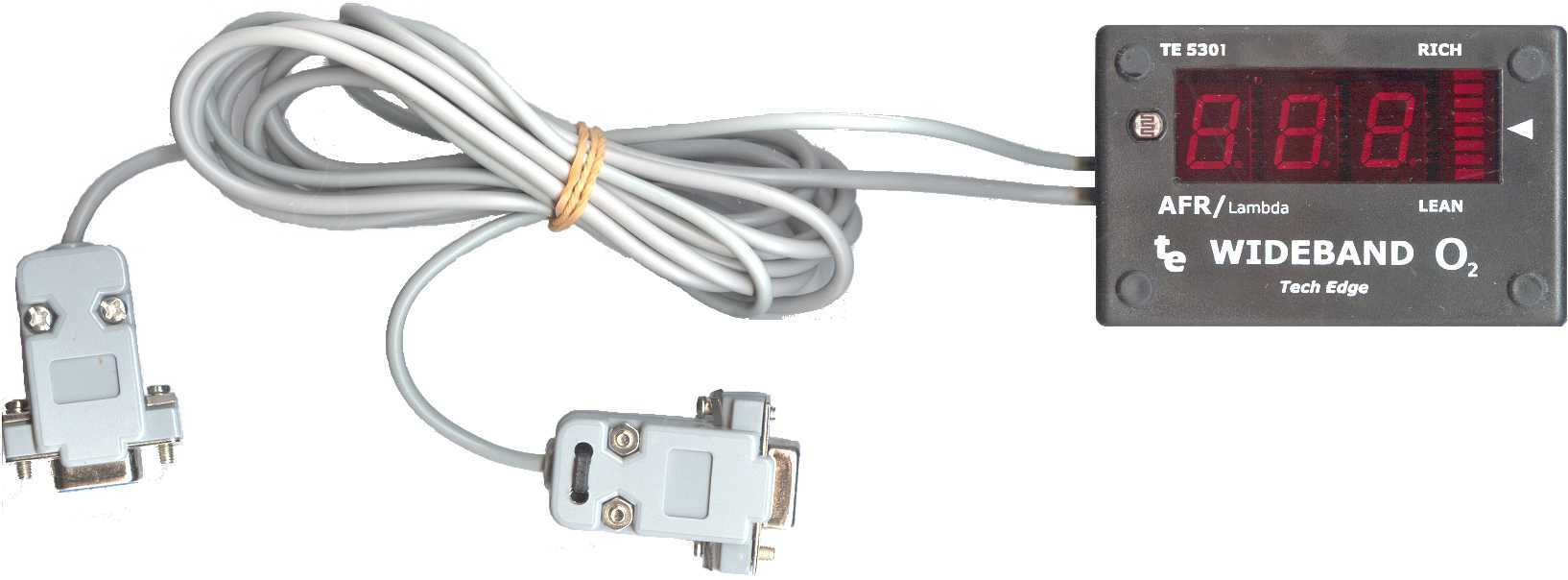
This image shows the 5301 with cables. The long cable goes to the wideband unit, and the shorter is the RS232 cable. The unit weighs about 160 grams (including cables), and is 84 wide x 54 high x 32 mm deep. More detailed technical information about the 5301 display, including a full schematic, can be found here. |
 |
 |
There are two connectors from the TE-5301. They are shown here looking at the female DB9 connector ends. they have small numbers printed on them for positive identification. The longer (and slightly thicker) cable connects to the WB unit and carries power to the display (pin 9), ground (pin 6), and wideband signal in (pin 7, called Vout on version 1.0, and Vwb on version 1.5). The shorter (and thinner) cable carries the RS232 signal (described below) and is designed to connect directly to a PC. |
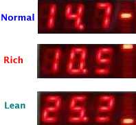 |
The display's three basic regions of operation are shown at left.
The display can also be modified (requires small changes to the hardware) to read in Lambda units. Also, the right 7 vertical segments can operate in bar mode as well as dot mode. The required modification are described below. |
There is third party Logging software, for both Windows and Palm, from Jonathan Burchmore.
We hope to have further logging software available as time permits.
The format of the data from the 5301 is quite simple. It is a 19,200 baud RS232 signal with a repetition rate of 5 characters per second and each character is the binary equivilant of the decimal AFR times 10. For example, a byte from the 5301 with value 7E hex (also expressed as 0x7E, or $7E, and displayed in ASCII as the ~ character) has a decimal representation of 126, and this represent an AFR of 12.6 from the WB unit.
|
Dot mode displays 48 unique LED configurations with a difference of 0.2 AFR between steps, from 10.0 to 19.6 AFR. Either one single LED is fully lit, or two LEDs are lit with a varying intensity, giving the impression the LEDs move slowly upwards as the display shows a richer mixture. The single centre LED is lit for AFRs between 14.6 and 14.7. |
 |
 |
Bar mode displays just 8 different LED configurations with a chunky difference of 1.6 AFR between modes. It does have the advantage of easily seeing how far away from stoic you are by comparing the total width of the lit bars. |
Lambda mode uses a different lookup table to convert the A/D value from the sensor into a different display value. Lambda is simply the ratio of current AFR to AFR at stoic. For petrol this is commonly calculated as AFR/14.7 (although strictly it depends on the fuel, different fuels have different values for the AFR at stoic).
AFR |
10 | 11 | 12 | 13 | 14 |
14.7 |
15 | 16 | 17 | 18 | 19 |
20 | 21 | 22 | 23 | 24 | 25 |
LAMBDA |
0.68 | 0.75 | 0.82 | 0.88 | 0.95 |
1.00 |
1.02 | 1.09 | 1.16 | 1.22 | 1.29 |
1.36 | 1.43 | 1.50 | 1.57 | 1.63 | 1.70 |
mixture |
rich |
stoic |
lean |
||||||||||||||
In Lambda mode the rich range is always shown with a 0 in the left display position. Lean is shown with a 1. This makes it easy to see immediately if a rich or lean condition exists. Small changes to the 5301 are required to select this mode (this is described below).
|
The startup display shows four important items. Refer to the diagram at right showing which LEDs relate to which mode. The default configuration is normal mode, displaying AFR with a 48 step Dot display. |
|
These options are . . .
|
 |
|
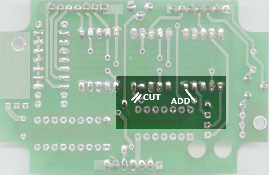
Changes to the 5301 unit for Lambda mode operation are made to the top (display) PCB and involve moving the wires that control the decimal point from its fixed position between the middle and the right digits, to between the left and middle digits. This is done by cutting one trace on the PCB, and adding another as shown in the image on the left (click on image for enlargement). More information on the 5301 can be found in the kit instruction pages. Once the changes are made to the PCB, an additional 1.8 k ohm resistor (not supplied with the unit) should be soldered into the R3 position on the same top PCB. |
Built 5301 units are shipped already pre-calibrated and normally don't require further calibration. 5301 units that are purchased with a wideband unit are pre-calibrated for that specific WB unit.
It may be necessary to re-calibrate the display, and these notes should allow you, or someone you know who is knowledgable about electronics, to perform the operation. It is possible to change the OFFSET control stightly to ensure the display reads 14.7 while the NTK sensor is warming up - any other changes, apart from the DIM control, should only be attempted with the correct tools and knowledge.
The SPAN, OFFSET and DIM controls are adjusted as shown below. Locating the controls is easy as the two PCBs have etched labels for each control.
The display PCB is wired temporarily with R2 = 1.8 k ohm (not supplied with pre-built units), do this simply by inserting (not soldering) the resistor no more than 1 mm through the holes from the component side of the PCB. After switching OFF, then back ON, the display will now show the SENSOR INPUT voltage in volts x 10, or alternatively, an out of range condition. You'll see either Lo, a value between 14.0 and 30.8 (representing 1.400 through 3.088 Volts), or Hi.
The calibration mode display actually shows 3 1/2 digits, the 1/2 digit is the dot/bar display, and is interpreted using the image at right (note that 0 is blank). However, as the firmware A/D converter is accurate to only 8 mVolts, the dot/bar display will give the appearance of "jumping all over the place" as it displays (say) 14.00 -> 14.08 -> 14.16, etc. - the dot/bar will jump from [blank] -> 8 -> 6, etc.
 A suitable voltage source for calibration can be obtained from an external 20 or 50 k ohm potentiometer
wired across a couple of fresh 1.5 volt batteries (which should each show at least 1.55 Volts).
An accurate DVM is used to measure the voltage input to the 5301 unit
(note: leave the meter connected during calibration to
ensure the test voltage is not influenced by the meter itself).
If you have a multi turn pot, then setting the test voltage becomes easier, although this is not essential.
A suitable voltage source for calibration can be obtained from an external 20 or 50 k ohm potentiometer
wired across a couple of fresh 1.5 volt batteries (which should each show at least 1.55 Volts).
An accurate DVM is used to measure the voltage input to the 5301 unit
(note: leave the meter connected during calibration to
ensure the test voltage is not influenced by the meter itself).
If you have a multi turn pot, then setting the test voltage becomes easier, although this is not essential.
OFFSET Adjustment : The 5301 unit is calibrated first at a minimum input voltage of 1.400 Volts (1400 mV) by adjusting R3, which is the 5 k ohm potentiometer (VR3 = OFFSET) on the processor PCB (right side hole). The display should read 14.0 and the dot/bar should be blank. Ideally, the OFFSET pot should be set to almost display Lo as this will be closest to 1400 mV.
SPAN Adjustment : For the other end of the range, it is calibrated at a maximum input voltage of 3.000 Volts by adjusting the 200 k (or 250 k) ohm potentiometer (VR2 = SPAN) on the processor PCB (left side hole). The display should read 30.0 and the dot/bar should be blank. Ideally, the SPAN pot should be set to almost display 29.9 as this will be closest to 3000 mV.
This procedure should be repeated as each adjustment may slightly affect the other. A quick check at other points in the displayed range of 1.40 to 3.08 can be made, but remember the DVM you use may have some linearity errors as well as the FMD circuit. The two displayed voltages should track such that the rightmost FMD digit is never off by more than one from the DVM's corresponding displayed value.
DIM Adjustment : This is difficult to do other than at night and in the vehicle itself. An approximation can be made by slipping a black pen cover over the LDR (out of the case) and adjusting the DIM control to just blank the display, and then turning the control a fraction to just turn it back on.
Use of an air-fuel meter for tuning purposes represents a potential hazard to the safe operation of your vehicle. Use of any display device within a moving vehicle present a safety hazard. Be warned you should consider having an assistant when using this device.

Assembler/Disassembler | 1227808 ECM | 8192 Baud ALDL | 160 Baud ALDL
Last updated 23 December 2002
Statistics by
www.digits.com
Shows approximate unique hits since 03 November 2001.
This document is Copyright © Tech Edge 2001 and
contains reference to material that is Copyright © Silicon Chip.
Previous |
Home |
Feedback |
Copyright