| NEW! |
we'll soon describe an alternative, possibly cheaper, two transistor circuit. Here's a sneak preview. We'll have 160 and 8192 baud software soon too (but see below for a range of free software available now). |
There have been a number of designs published (none by GM) to enable the GM proprietory ALDL data stream to be tapped into. Our design uses a MAX232 (or MAX233) because this is the simplest way to do it. We also avoid using a separate power supply by powering the MAX chip from the PC's serial port (DTR and RTS signals must be set to +ve).
This circuit can also be used to read older ECU's 160 baud ALDL signals. Here's our circuit using the MAX232 (or MAX232A). Vehicle signals are on the left, PC signals on the right, with DB9 (and DB25 in brackets) pin assignments shown (pin N on DB9 is N/9, etc.).
Note that the 3.3 uF capacitors (C1-C4) may be reduced to 1 uF if these are readily at hand, or to 0.1 uF if you use the MAX232A. If you use a MAX233, which has a different pinout to the MAX232, you don't need to use any of the capacitors C1-C4, but the regulator still requires C5 and C6. More information is available from Maxim, or you can download the data sheets for their 5 Volt Interface Products. As well, get the 78L05 data sheet from Natsemi, and the IN914A data sheet from Fairchild.
Early ECUs produced a fixed 8192 ALDL data stream when the user placed a 10k ohm resistor between ALDL connector pins A and B. Later ECUs added internal receive circuitry (the SXR Delco/Delphi transceiver chip). for enhanced capabilities, and their firmware was upgraded too. Software can be used to enable the 8192 ALDL data stream from these later ECUs.
The 8192 baud Rx and Tx data to/from the PC is combined with a diode and resistor (D3, R1) before being sent to the ECU. The 160 baud data is sent to the PC and appears as a toggling CTS signal. thus no mechanical switching is required to select either 160 or 8192 baud data streams.
The diagnostic sense resistor R3 may not be required for later ECUs where software controls the ALDL data.
The power supply uses two signal lines (RTS and DTR) from the PC to provide a positive voltage for the MAX chip. The two diodes (D1 and D2) are used to ensure power is available even if only one signal line is positive. Capacitor C6 ensures the low power 78L05 regulator is stable in operation. Capacitor C5 provides decoupling and filtering from the PC. C1 through C4 are the charge pump and inverter capacitors - their orientation (assuming you use tantalum types) should be double checked.
To our knowledge, there have been at least four different ALDL connectors used world wide (and probably more exist too!).
Tell us about them!
In Australia, the VN and VP models used a 6 pin connector.
The diagnostic link, a paper clip (red dotted line), is used to enable
"flashing diagnostic mode", and is not described here.
The data from this connector is at 160 baud when the diagnostic link is a 10k ohm resistor.
You'll find this connector under the glove box on the VN/VP.
Connectors
6 Pin Australian connector
 |
Here's a view of the 12 pin US style ALDL connector, and where to connect the above circuit to. The pin numbering scheme is the same as that used on the VN/VP Holden Commodores (but those vehicles used the 6 pin connector shown above). This connector is also found in the Holden JE Camira and the Nissan LE Pulsar. This diagram is courtesy Carsten Meyer.
Later Australian Commodore models (VR, VS, etc.) use a 16 pin OBD-II style connector, but the pinouts are unique to Australia. This connector is located under the steering wheel.
European Opels use a 10 pin connector. Image courtesy Bert de Boer of Holland.
A number of people have produced free software of varying complexity and platform support
that will work with the above interface. We don't have any 8192 baud software yet, but we do have
160 baud simple and generic software for DOS.
Here's a short list of some of the people/web pages I've come across
(under construction, and in no particular order, tell me if you find
a broken link,
or you have
another link to add).
If you have a free ALDL program that will work with the above hardware,
then send me eMail
and I'll attempt to include you here.
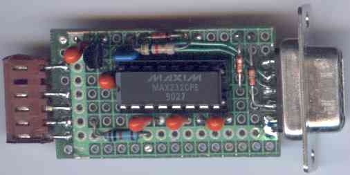
Here's a picture of the prototype constructed on a plated thru' prototype base.
Note the connector on the left hand side that goes to the vehicles ALDL connector via a
"patch plug" (not shown) that will suit your particular vehicle and ALDL connector.
The right side connector is a DB9-S (solder tail style) that plugs direct to my laptop for in-car use
or to a long RS232 extension cable for remote operation on my desktop PC.
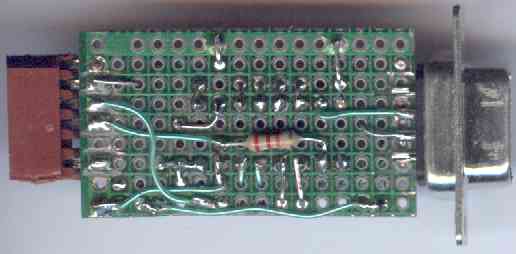
Here's the other (solder) side showing the 22 k ohm resistor.
The assignments of the 6 pin connector on the left are (pin 1 has a black stripe on connector body,
ie. bottom of top picture):
Software - 160 & 8192 Baud
Prototype Hardware - Construction
    Pin  Schematic     Assignment
     1       A      Vehicle GND
     2       B      10 k ohm - Mode Select Resistor
     3       M      8192 Baud Data Stream
     4       E      160  Baud Data Stream
     5      n/c     Polarisation marker (plugged)
     6       H      Vehicle +12 Volts
Note that pin 5 is plugged to prevent the "patch plug" from being inserted the wrong way.
Another thing to watch, if you use a plated through prototype PCB as I have done,
make sure that you drill the pads off one side of the board under the DB9.
The second photo shows this rather indistinctly.
If you don't do this then you'll inevitably get a short from one side of the DB9 to the other.
Statistics by www.digits.com
Shows approximate unique hits since 30 March 2001.