This interface allows the vehicle's ALDL data stream to be displayed in real time on a PC using simple software. The hardware is designed to be able to be constructed by the average hobbyist who has a temperature controlled soldering iron and basic skills in constructing simple electronics. It uses a minimum of (readily available) components consistent with good electronics design.
I describe here one of the simplest 160 baud ALDL interface that connects to a PC's serial port. Because RS232 cables can be quite long, and can pick up electrical noise easily, the serial port was chosen as the PC interface.
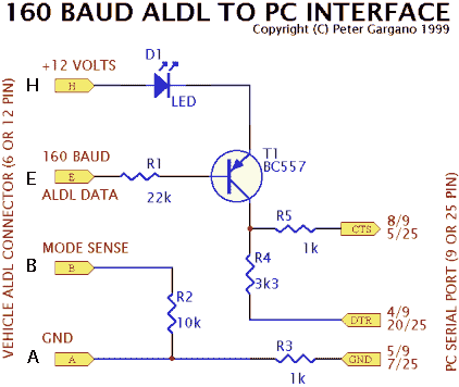
The design uses one transistor, 5 resistors and an LED for diagnostic display purposes. A schematic and also a component and solder side view of the prototype are shown here.
The transistor (a general purpose PNP transistor, like the BC557 or 2N2907) is used as a level converter for the 0 to 12 Volt levels from the 160 baud ALDL data stream to the RS232 levels expected by the serial port. The LED is used as an indicator of the 160 baud data stream and also to ensure the transistor is cut off when the ALDL data is HI.
When the ALDL signal is close to 12 Volts (the dash Check Engine Light will be OFF) the transistor will be turned off and its collector will be close to the (negative) DTR level (from pin 4 of 9). The DTR pin is set by the software to a negative RS232 level so that the level read on CTS (pin 8 of 9) will also be negative.
When the ALDL signal is close to 0 Volts the transistor will be saturated and drawing its maximum collector current. Collector voltage will be close to 12 Volts less the voltage drop across the LED and the transistor's Vces. The CTS input will be at a positive level which will be compatible with a positive RS232 level.
The RS232 levels on CTS are inverted by the PC's RS232 receiver and again by the PC's 8250 serial controller (or variant such as the 16550) chip. The level read from the 8250's modem status register will reflect the level at the transistor's collector. Put another way, as the transistor also inverts the signal, the 8250's status register will read a 0 when the ALDL data is at 12 Volts, and a 1 when the ALDL data is at 0 Volts.
The parts are almost junk box components and most hobbyists will have no trouble obtaining these parts. I used a BC557 transistor but a 2N2907 should work fine too. The resistors are 1/4 watt metal film parts but anything that is physically compatible should work fine. Using perforated board for construction may make your version more robust and easier to construct but it can equally be built in "free air". You may think about building the unit so it fits into a DB9 or DB25 plastic shell, but make sure you anchor the ALDL cable to the circuit as this will be one of the first points of failure.
   BC557   (or 2N2907) - General purpose PNP transistor
   LED     any GP LED  - prototype used a green LED
   1k x 2  resistors   - (black-brown-red)
   3.3k    resistor    - (orange-orange-red)
   10k     resistor    - (black-brown-orange)
   22k     resistor    - (red-red-orange)
   DB9S    connector   - or DB25S (socket=female) as appropriate for your PC

   perforated board, solder, wire, etc. (optional DB shell or case)
The connections A through H on the schematic are connected, via another cable with appropriate plugs, to the vehicles ALDL connector. There are at least two vehicle ALDL connectors that are used worldwide (and probably many more!). The following details are by no means exhaustive. Note that the connections are shown as one would see when viewing the connector from it "front", or the end that plugs into its mating connector. Some connectors may actually have markings on them indicating the pin's numbering.
The Australian VN and VP Holden Commodores (1988-1992) were the first Australian Holdens to have a Delco/GM EFI system. The ALDL connector is found under the glove box compartment, close to the ECU. Shorting pins A and B (with a paper clip?) will enable the vehicles "flashing diagnostic codes" mode.
       -----------        Mating connector type XB4 (make unknown)
       | G E F B |
       | H     A |        GM "Tech 1" mating connector TA02329A
       ----| |----
           ---

Pin  Function
 A   Earth, 0 Volts
 B   Diagnostic test terminal
 F   Torque converter clutch
 E   Check engine light (CEL) and ALDL data (0 to +12v)
 G   Fuel pump test
 H   +12 volts
           -----------------------
         --| F | E | D | C | B | A |--
         | |-----------------------| |
         --| G | H | J | K | L | M |--
            -----------------------
     North American ALDL connector pinouts
This connector is found in many North American vehicles of the mid to late 1980s and early 1990s.
Pin  Function
 A   Earth, 0 Volts
 B   Diagnostic Terminal, (short to pin A to activate diagnostic mode)
 C
 D
 E   160 baud ALDL Serial Data.
 F
 G
 H   12 Volts (switched from Ignition)
 J
 K
 L
 M
I built a prototype of the interface on a piece of perforated board. Both sides of my prototype are shown below. I used a DB9 (9 pin) connector but the schematic above also shows the corresponding DB25 (25 pin) connections should you wish to use that connector instead. Whichever DB plug you use you can readily obtain an 9->25 or 25->9 pin adapter for use with PCs having the other DB plug. On your interface, the LED should be mounted on the side that most suits your PCs serial port orientation. The LED has a diagnostic use as well as being a part of the electrical design, it cannot be omitted. Note also that the LED will be OFF when the vehicles check engine light (CEL) is ON. When the ALDL data stream is being read, both the LED and the vehicles CEL lamp will flicker irregularly.
The connector to the left in the above pictures does NOT connect directly to the vehicle's ALDL connector. Another cable, with corresponding plugs, adapts to each connector. This was done so that a short cable for in-vehicle use and a longer cable for workshop use can be use as appropriate.
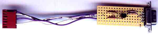
The component side of the prototype 160 baud ALDL interface showing the transistor and 4 resistors.
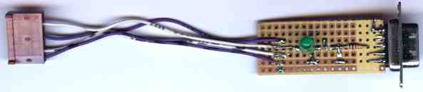
The solder side of the prototype 160 baud ALDL interface showing the green LED and another resistor.
Simple software to display the raw ALDL data stream is available on this site. It is not designed to be fancy, but provides enough information to diagnose many simple ECU and vehicle EFI problems. Tech Edge intends to make a more complete feature packed package that will be available at low cost from this web site. If you wish to be informed of the availability of this software then we'll contact you as soon as we have completed our prototype.