Silicon Chip Fuel Mixture Display
TE-WB (v1.5)
| Oz DIY-WB (v1.0)
| TE-5301
| Wideband FMD
| Silicon Chip FMD
|
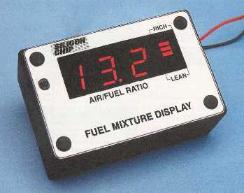
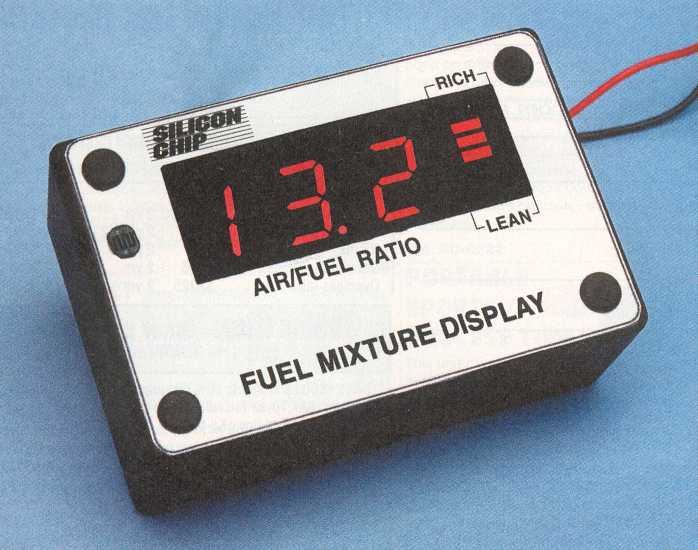
The image shows a Dick Smith version of the original FMD designed for the Bosch LSM-11 sensor.
Here's an image of the Jaycar version.
A more accurate wideband fuel mixture
kit using the NTK L1H1 UEGO sensor is available from Tech Edge.
The Silicon Chip September and October 2000 issue
features a fuel mixture (or air/fuel ratio) display.
This display is offered as a kit or just a set of two PCBs by (prices correct @ 31 Oct 01):
It features
- Digital readout plus bargraph
- Display auto-dims at night
- Calibrated for Bosch LSM-11
- 11.8 to 20.6 AFR range for petrol
|
The Design
It uses a commonly available MicroChip PIC chip,
the
16F84 (the lowest cost 4 Mhz version) which is a mature and readily available flash part
that can be
reprogrammed
easily.
The unit is built on two small single sided PCBs with just a few jumpers.
The boards fit together with no messy inter-board wiring.
One PCB holds the display components and the other the PIC circuitry.
Just three wires connect to the vehicle - the sensor, Vbatt and GND.
The circuit below also has a larger view
(1485 x 1086 = 218k bytes).
Software for the project is available as
zipped source form or
zipped hex
from Silicon Chip's web site
The input from the Bosch LSM-11 sensor is via a 1M ohm resistor and 0.1 uF capacitor.
This results in very low loading of the sensor but also damps any noise and slows
the response to a readable rate - display refresh is around 2.5 times a second for
the 3 digits, and twice that for the bar display.
The charge pump and regulator circuit Q6, D1, D2 and REF1 generate a small negative
voltage that is used in conjunction with comparator IC2a and the PIC to create an
eight bit analogue to digital (AtoD) converter using just two pins of the PIC.
A square wave at 1953 Hz, and varying in duty cycle, is generated at RA3. The PIC's
firmware varies this duty cycle to create a reference voltage at the comparator's
+ve input pin 3 that is compared with the sensor's output voltage.
The PIC uses a lookup table to convert the voltage read from the sensors into an
air-fuel ratio to multiplex onto the 3 seven segment LED displays and just 7 segments of
the 10 segment dot/bar display. Transistor Q6, opamp 2b work with the light
dependant resistor and VR1 to provide adjustable automatic dimming at night.
Transfer function
The unit comes with the sensor voltage to A/F ratio transfer function shown in the
graph (click on diagram for a
larger view
and details of how the dot/bar display is
interpreted - 716 x 1144 = 152k bytes).
As the source code for the PIC is provided, this transfer function can be modified
to suit different sensors - including the
DIY-WB unit's usable
output swing of around 2.7 volts (1.4 - 3.1).
|
|
Modifications for DIY-WB operation
Modifications for operation with the
Oz DIY-WB electronics
are quite simple and can be done for around a dollar (although the PIC must be reprogrammed).
Full
details of all modifications,
are available, but note that this design uses an NTK sensor that is
quite different to the Bosch LSM-11.
The NTK sensor requires the additional electronics provided by the DIY-WB unit.
Last updated 22 December 2002 (links)
Statistics by  www.digits.com
Shows approximate unique hits since 26 August 2001.
~2500 hit at 16th July 2002
The document contains reference to material that is © Copyright Silicon Chip.
This information is provided under the
fair dealing
copyright clause of the
Act.
This document is © Copyright Peter Gargano 2001, 2002
Previous |
Home |
Feedback |
Copyright