NTK sensor to Oz-WB Unit Cable
Previous
| Order Page
| Wideband
| 2.0 Info
| 1.5/1.1 Info
| 1.0 Info
| Cable
| TE-5301
| NTK L1H1
This page is designed to help you construct your own NTK sensor to WB unit cable.
We show you how we construct the cables we sell for versions 1.0, 1.1 & 1.5 (there were
a very small number of version 1.0 units that didn't use the circular 8 pin connector).
Note that we don't sell the actual wire cable or the sheath used in the cable, but
the connectors for either end do come in the kit(s).
Cable Connections
|
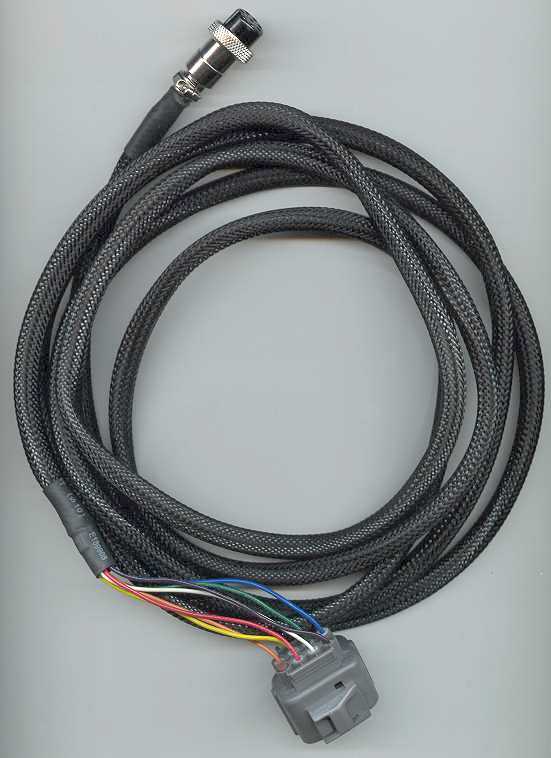
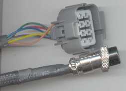
This diagram shows the complete signal path from the WB unit to the NTK sensor.
The colours are those used on the L1H1 sensor (L2H2 sensor uses different colours).
At the left is the 8 pin circular metal male connector on the WB unit,
and it mates to the female circular connector of the cable.
In the middle are the grey Sumitomo connector ends (female=cable, male=sensor).
The sensor end of the connector houses the calibration resistor (CalR).
|
|
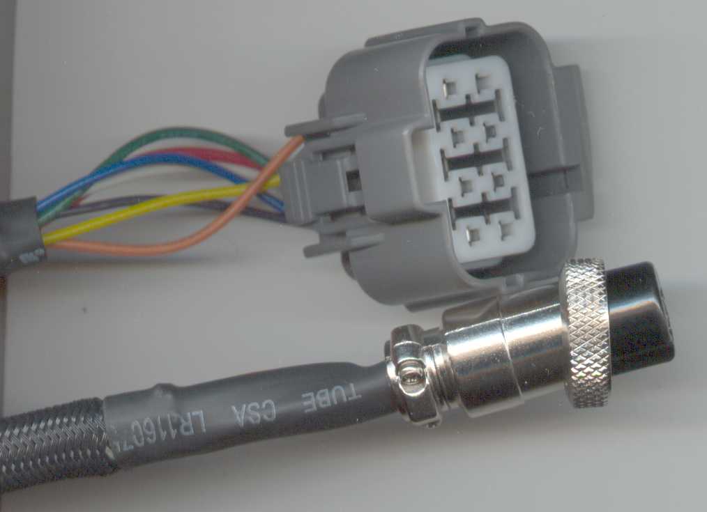
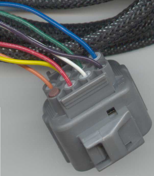
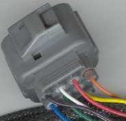
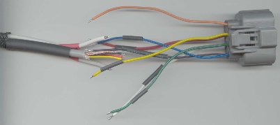
Sumitomo Connector Numbering
The grey Sumitomo connector does not have any pin numbers
marked on its body and we have assigned numbering as shown in the image at right.
The connector is viewed from the back of the mating surface where the wires enter.
The image outline only matches exactly if you have the connector oriented
correctly as shown in the image at left. This image also shows the colour
of the wires used and their exact location.
|
|
|
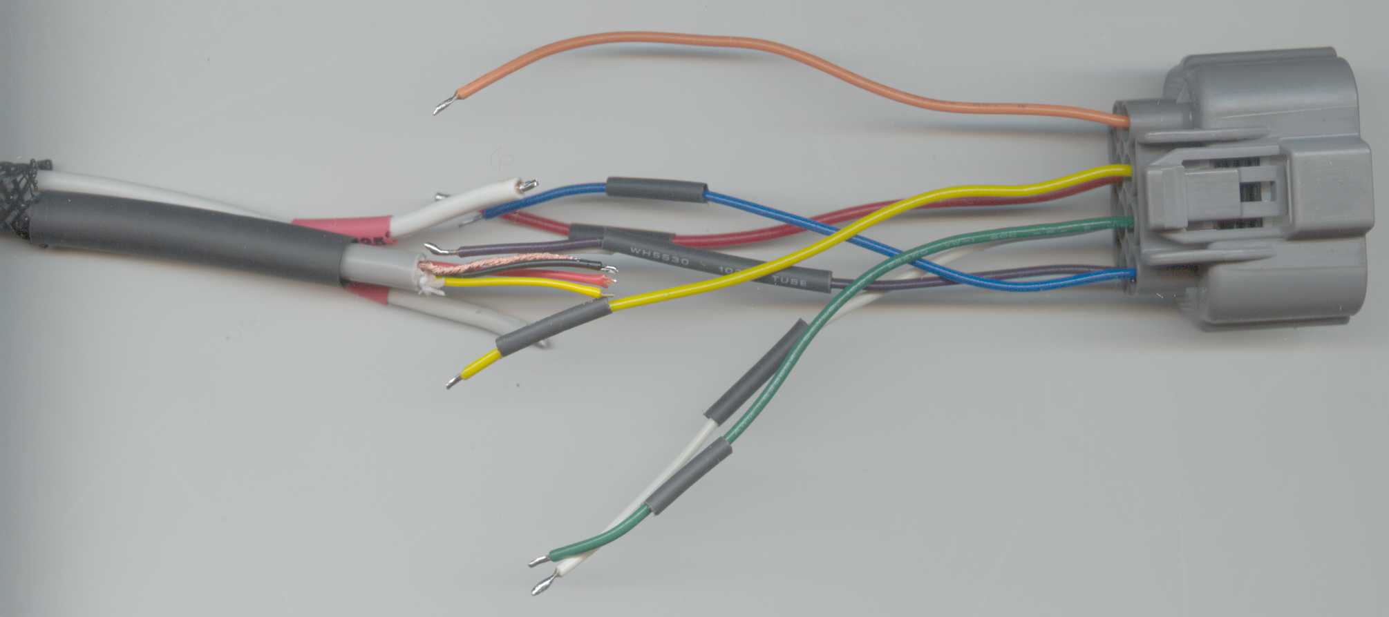
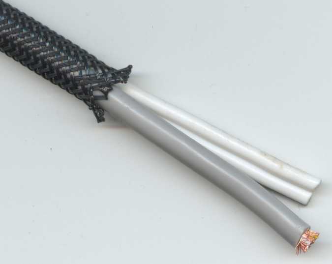
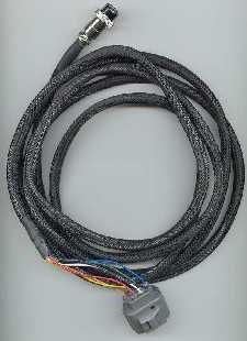
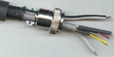
Internal Cable Detail
The complete cable is made up internally of two different cable types and a third
set of connector wires at the sensor end of the cable.
A very light gauge 4 core cable with individual shields carries all the low current signals
including the calibration resistor wires.
A much heavier figure 8 cable carries the heater current on wires H+ and H-.
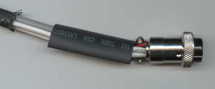
The two cables are covered in a heavy duty woven nylon sheath and
heatshrink is used to cover connections that are made between the thinner
inner conductors and the heavier end wires.
|
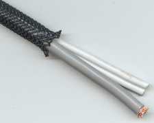
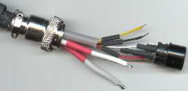
Wires Details
Click on the image at right to get an idea of the wire sizes we use for
the three different types of wire we use, and how we connect the coloured wires,
at the Sumitomo connector end, to the shielded cable and the figure 8 cable.
The 4 core shielded cable is very light duty cable intended for audio applications
(such as the Jaycar
part # WB-1510).
The figure 8 heavy duty cable is the type commonly used for single shielded 24/020 (24 strands of 0.20 mm diam.)
AC mains cables (such as the Jaycar
part # WB-1708).
|
|
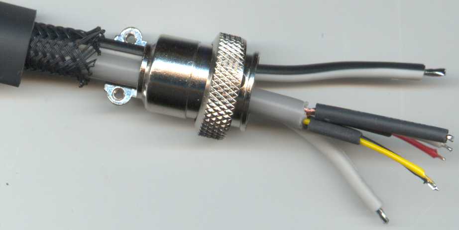
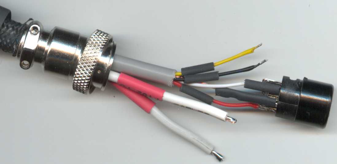
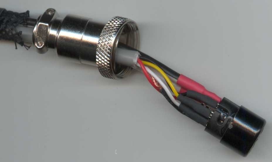
Cable Construction Images

8 Pin Circular

Sumitomo Connector
See the Sumitomo connector information page.
Last updated 22th May 2003.
Created 17th July 2002.
This document is copyright © 2002, Tech Edge Pty. Ltd.
Previous |
Home |
Feedback |
Copyright