NTK L1H1 Sensor Information

Tech Edge WideBand     |     NTK L1H1 UEGO Sensor     |     Technical Data     |     Sumitomo Connector
NTK sensor

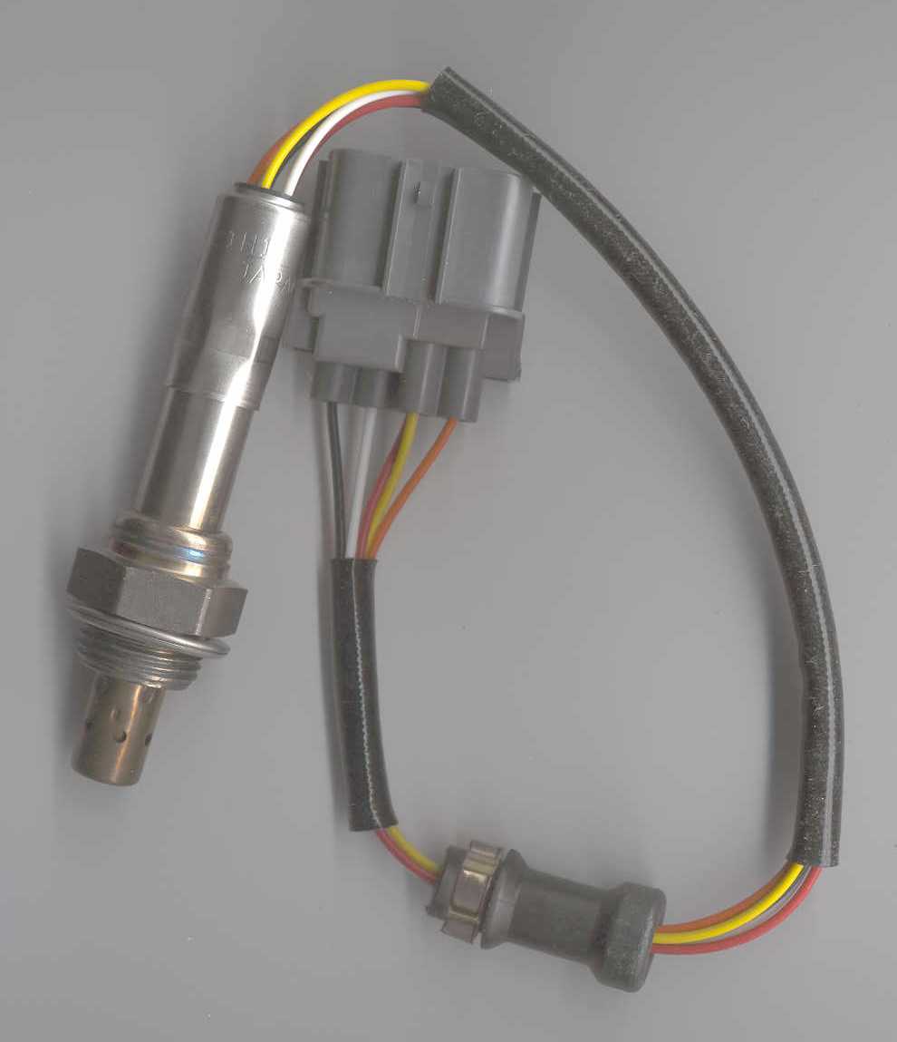
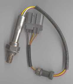
The single most expensive and vital component of the DIY-WB kit is the NTK wide band sensor (also called a UEGO, or Universal Exhaust Gas Oxygen sensor).

The DIY-WB kit works ONLY with a specific 5 wire NTK sensor (with a 7 pin plug). This sensor is available as a replacement part for a Honda (part # 36531-P07-003 - Honda Civic 1.5 3 Door, circa 1995, US, non-Californian model).

The NTK sensor is stamped with the text L1H1 and is often referred to using this name. Napa have recently found stocks of the L2H2 and we have found this sensor works too. Any other sensor will not work and may damage your DIY-WB circuit. The sensor requires an 18 mm bung with 1.5 threads/mm pitch (this is one of the standard lambda sensor & sparkplug base sizes).

The following can supply the correct NTK sensor. Note that the links may not always show the correct part if they are out of stock.

NTK sensor
click on image for enlargement

L1H1 NTK sensor in Bosch Box

The correct part will be an NTK sensor although the box it comes in may say Bosch (as in the image shown here), Echlin, etc.

click on image for enlargement

You will also need a cable with a Sumitomo connector.

How the NTK Pump Cell Sensor Works

Briefly, the NTK sensor requires a controller because it is more complex than a standard switching type sensor. It's made up of a narrow band oxygen sensor (the Reference Cell in the image) coupled to a pump cell and a small diffusion chamber. The electronics (in the WB unit case) are represented by the yellow and green symbols.

The pump cell, in conjunction with a catalytic reaction at the surface of the cell's electrodes, can either consume oxygen or consumed hydrocarbon fuel in the pump cell cavity, depending on the direction of the Ip current flow.

In normal sensor operation, a small sample of the exhaust gas passes through the diffusion gap into the pump cell. That exhaust gas is either rich or lean and both conditions are sensed by the reference cell which produces a voltage Vs above or below the Vref signal (this voltage has the characterictics of a narrow band switching type sensor).

A rich exhaust will produce a high Vs voltage and the electronics produces a pump current Ip in one direction to consume the free fuel. A lean exhaust produces a low Vs and the electronics sends the pump current in the opposite direction to consume free oxygen.

When the free oxygen or free fuel has been neutralised, the Vs feedback signal goes to about 450 mVolts (the same as the Vref value). The pump current required to produce this equilibrium is a measure of the Lambda or Air Fuel Ratio. The electronics in the WB unit converts the Ip into a Vout which is the output of the WB unit. Not shown is the Rcal, or calibration resistor, in the sensor's connector which compensates for manufacturing variations between sensors.

Here are some representations of the Vs or narrow band Sense Voltage (left) and Ip or Pump Current characteristics described above. Note that the narrow band graph's x-axis covers only a very narrow lambda range (+/- 0.02), whereas the wideband's x-axis covers the range 0.9 to 2.2.

This graph shows the actual Vout of the DIY-WB unit. Note that the curve takes the same general shape as the above Ip graph.

In particular, note that the rich and lean regions have a different slope. This occurs because the chemical reactions in the rich and lean regions are fundamentally different, and the magnitude of Ip has a different effect in each region.

For more information about the DIY-WB's AFR or Lambda curve see the technical data section here.

Here's some information from Bosch USA about their narrow band LSF-4 and their wideband LSU-4 sensor. The LSU-4 is similar in operation to the NTK L1H1 (although they are not interchangeable at all).

And here's another Bosch information paper (300 k PDF) about oxygen sensors in general, with specific reference to their wide band lambda sensor (ie. the LSU-4).

... more info here as soon as time permits ...

If you still have any questions on the Oz DIY-WB parts kit then email us.


Previous | Oz DIY-WB Home | Order Oz DIY-WB parts/units | Copyright

logo

Last updated 18 June 2003. | any broken links on this page?

Copyright © 2002 Tech Edge Pty. Ltd.

Previous | Home | Feedback | Copyright