
Wideband | 1.5 Info | Built | Kit | 1.5 Technical | Wiring | Fixes | debugging | Software | Calibration | Schematic | NTK L1H1 | 5301 display
|
The 1.5 unit has been supersceeded by the WBo2 or version 2.0 unit. This document describes the Tech Edge version 1.5 wideband unit's technical specifications. Inputs and outputs including software protocols are detailed. Refer to the schematics for a more detailed insight into the unit's operation. Version 1.5 improves on the specifications of the earlier version 1.0 unit. |
|
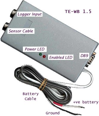
Refer to the above image showing the battery cable entering the unit from the right. The cable is colour coded with a single RED heatshrink band indicating the Positive battery connection wire that should be connected to a switched point on the vehicle that is activated when the ignition is turned on. The other wire connects to the vehicle's ground, and preferably as close to the battery, or ECM as possible.
Resist the temptation to connect the battery cable to a cigarette lighter plug as these tend to be unreliable. Remember also that the sensor should NOT be run with the heater disconnected as a cold sensor will rapidly clog up (perhaps irreversibly) with carbon deposits that are burnt off during normal operation.
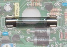
The WB unit draws up to 1.5 Amps during normal operation and the battery voltage should not drop below 11.0 Volts. The WB unit is protected from reversed battery polarity by an inbuilt 3 Amp fuse that will also "blow" if there is an internal short. The image at right shows the location of the 3AG 32x6mm fuse in the centre of the PCB. Always replace the fuse with a similar 3 Amp version.
|
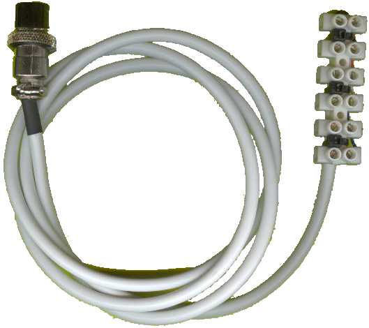
One of the biggest changes from our version 1.0 (Oz-DIY-WB) unit is that version 1.5 now offers the capability to capture and log wideband (AFR) reading, two extra analogue channels, and RPM. Captured information is made available at the RS232 output in the form of a data frame that can be saved on a PC or PDA (see later for full RS232 frame information). The terminal block block at the end of the D/A cable is shown at right. Pin 1 is at the end of the cable. Pin assignments, cable colours, and pins used on the connector plug are shown in the table. |
|
|
Pin 1 & 2 of the terminal block are user voltage inputs in the range of 0 to 5 Volts. They can be connected to sensor inputs such as MAP, TPS, and other analogue signals that may be need to be correlated against AFR. Pin 3 carries the simulated narrowband output for connection to an ECU (see technical information and WARNINGs below). Pin 5 & 6 are two alternate RPM inputs that can record engine speed. COIL is for direct connection to a traditional coil and distributor based system and should go to the switched side of the coil. RPM Low is for connection to a low voltage signal such may be available if your system uses a coil driver pack connected to an ECU. |
Note : Some extra circuitry may be needed to correctly sample and condition the signals available in your engine bay. Noise and/or weak signals may require your extra attention for successful RPM logging.
Simulated Narrowband Output NBout - D/A Pin 3The graph shows how the simulated narrowband output rapidly switches from a high value of around 1.0 Volts to a low value of close to zero volts. This occurs at a point that is user settable using the NB-SET control (inside the WB unit case). Remember that most vehicle ECUs are set to switch at a narrowband voltage of 450 mVolts. In this example the 450 mv NBout signal occurs at a Vout of ~2.517 mV which, using this Vout vs AFR graph, corresponds to an AFR of around 14.86. This means the NB set control has shifted what the ECU thinks is an AFR of 14.7 to a real value of close to 14.9, or almost a 0.2 AFR LEANER stoic setting. |
|
|
|
WARNING -- Although we don't recommend it, it is possible to change the closed loop AFR (used during highway cruise, and low throttle settings) to be either richer, or (in this case) leaner. Remember, this can cause your vehicle to overheat (running too lean) or to foul the plugs and cause premature wear (running rich). Use the NBout for extended periods only after you have assured yourself of the long term viability and safety of doing this. Refer to the Calibration & Setup Guide for details on how to setup or modify the NB set control. |
|
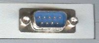
The male DB9 connector (known as CON3 on the schematics) carries a number of output signals as well as an RS232 output signal. Note that it is NOT an RS232 connector and a PC/Palm serial or null modem cable should NOT be connected directly to the connector as this may interfere with the operation of the WB unit. |
|
|
![]() Note : (**) that in the above table,
the pins 3 and 8 are reserved for the
indicated possible use, but are NOT actually connected that way on pre-built units.
Note : (**) that in the above table,
the pins 3 and 8 are reserved for the
indicated possible use, but are NOT actually connected that way on pre-built units.
AFR Output Voltage - Vout - Pin 7The measured AFR is output as a voltage (Vout) on the DB9 connector's pin 7. Beside it (pin 6) is a matching GND point. Vout (represented in the image as the pump current Ip mA) varies between about 1.0 Volt for a very rich mixture (AFR=9), to 2.50 Volts for a stoic mixture, and to 3.1 Volts for a lean mixture (AFR=25). In free air the Vout should be 4.00 Volts. The AFR vs. Vout relationship is the same as for the original Oz-DIY-WB and shown in the Vout table/graph page. The analogue Vout is a continuously available signal that may be logged with a high speed logger. We recommend at least a 10 bit converter for best accuracy. |
|
|
A synthesised linear wideband voltage is produced by the onboard microcontroller using a 10 bit A/D converter, a 187 point conversion lookup table (with linear interpolation), and an 8 bit PWM output (running at 10 kHz). At least 20 samples/second are converted and the output is suitable for a low speed logger with not more than 8 bit accuracy (such as that provided by a logging ECM). To convert the Vlin voltage to an AFR simply multiply the Vlin voltage by 2 and add 9. This is shown in the graph at left. The advantage of a linear output is that it's easy to write a conversion function from Vlin to AFR. |
|
The onboard Atmel ATtiny microprocessor produces a serial RS232 data stream at 19,200 baud (8 bit, no parity). The information logged is shown at right, in the order that it's delivered in a data frame. The first 3 (bytes 1, 2 & 3) and last (CRC byte 12) bytes allow the receiving computer to correctly synchronise with data and to check that data has not been corrupted. The frame sequence counter simply counts from 0 to 255 and then repeats, and allows the receiver to keep track of possible lost data frames. The bytes 4 & 5, 6 & 7 and 8 & 9 are really high and low byte pairs (ie. Motorola format) of four 16 bit values. Each of these two bytes is really a 13 bit value in the range 0 to 8192 representing a voltage between 0 and 5.00 Volts. The actual measurement is made at an accuracy of 10 bits and is averaged over 8 samples for each of the 4 inputs (ie 32 interleaved samples). Bytes 10 and 11 measure how many 5 microsecond time periods are counted between successive positive pulse edges on the COIL or RPM Pulse input pins. As the frequency of the pulses increases (RPM goes up), the count goes down. For a four cylinder 4 stroke engine (that produces two spark events per revoluntion), at 6,000 PRM there are 100 revolutions per second and 200 spark events and therefore the COIL input will measure 5,000 microseconds between sparks, or an RPM count of 1,000 for bytes 10 and 11. Note that if the pulse rate is lower than 20 per second then the unit will "time out" and return an invalid count. |
Data Frame Format
|
The RS232 driver produces an output between 0 and Vbatt (say 12 Volts). This is fine for the majority of PC and PDA RS232 receivers as they will happily operate this way (it's outside official RS232 specs).
Use of an air-fuel meter for tuning purposes represents a potential hazard to the safe operation of your vehicle. Use of any display device within a moving vehicle present a safety hazard. Be warned you should consider having an assistant when using this device.
Further information will be added as necessary (last major update on 28 June 2003) ....
Last updated 10 July 2003
We appreciate your feedback on the content and any corrections necessary to this article.
Previous |
Tech Edge Home |
Oz-DIY/TE WB Home |
Wideband Order Page |
Copyright

Page created th29 May 2003
This document is copyright ©
2002, Tech Edge Pty. Ltd.
Previous |
Home |
Feedback |
Copyright