We now offer the CX or completion kit that contains a tough ABS plastic case,
a pre-drilled heatsink, external connectors and other screws, nuts, bolts and
internal wiring. This kit allows you to finish your unit to the same high
standard of the fully
completed Oz DIY-WB
that is available from time to time.
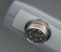
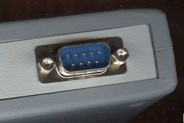
The NTK sensor is connected to the unit via a circular connector (top left of image),
and the WB unit's output goes to a DB9 (bottom right).
Not shown is the battery power/GND wire that exits the case just below the DB9 connector
on the image here.
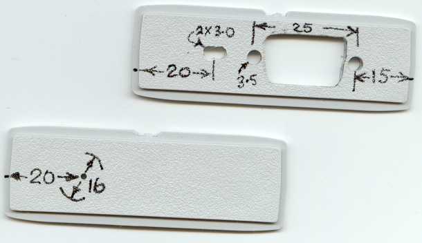
The two end plates of the case must be drilled before mounting the 8 pin circular connector
and the DB9 connector.
See an enlarged end plate drill image, or click on the image.
For the circular connector we use a multi-step UNIBIT "drill" set to give a 16 mm (5/8") hole
(you can use a small drill and drill a few holes for the same effect,
but be careful of the bit biting into the plastic).
For the DB9 we use the same bit and use it as a "router" after first marking a
template. The DB9 hole is covered by the DB9 itself, but ensure the hole is not
so large as to extend beyond the 12.7 mm (1/2") limit of the DB9.
The two 3.0 mm holes are for the figure 8 power cable and should be just large
enough to match the cable you provide yourself.
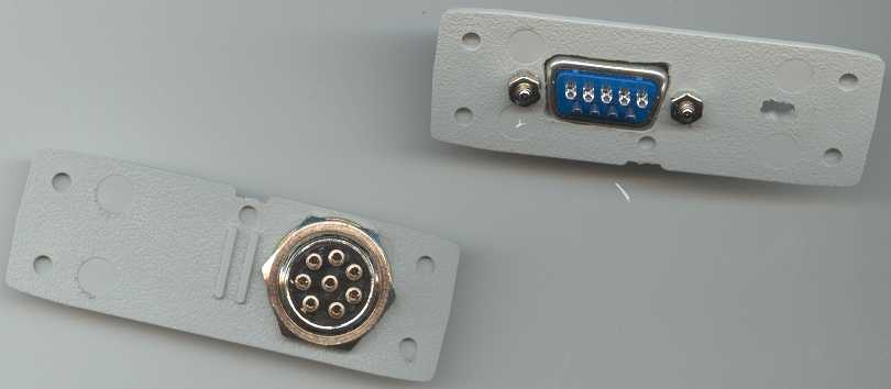
This is a thumbnail image of the connectors bolted to the end plates.
Click on the image for an enlargement.
We have not wired the connectors, but note that there are small numbers
beside each pin to ensure you wire the correct pins.
We orient the circular connector so that the locating tab of the
housing will be at the bottom (this enables you to see the locating
tab more easily, preventing incorrect insertion).
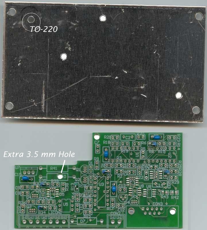
Heatsink and PCB Preparation
The pre-drilled heatsink has four outer 4.0 mm holes to allow the
aluminium plate to be bolted to the case using the four 3.0 mm (called M3) bolts and
four star washers. The image (see an enlargement)
shows three highlighted holes that mount the PCB using three 3.0 mm white nylon
threaded stand-offs.
The PCB must be drilled with an additional 3.5 mm hole directly through the closed
part of the R text of R40. First check that this hole matches the hole in the heatsink.
Note that the heatsink may come with a circled hole (near top left of image) indicating the PCB side and
the location of the insulated washer for the TO-220 regulator (use the image if not).
The M3 bolts and the threaded standoffs should be installed and the PCB location checked.
There should be no possibility of the PCB shorting to the bolt closest to the centre of the heatsink.
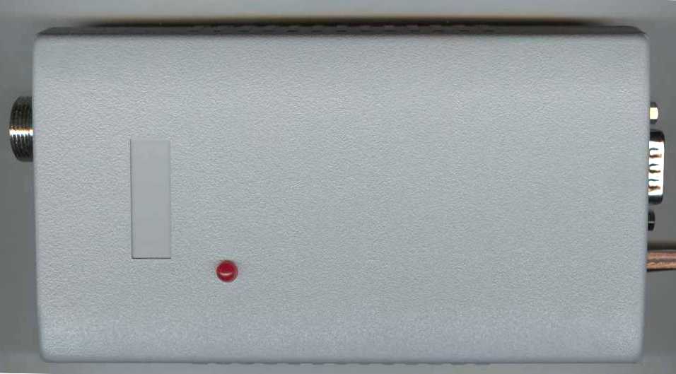
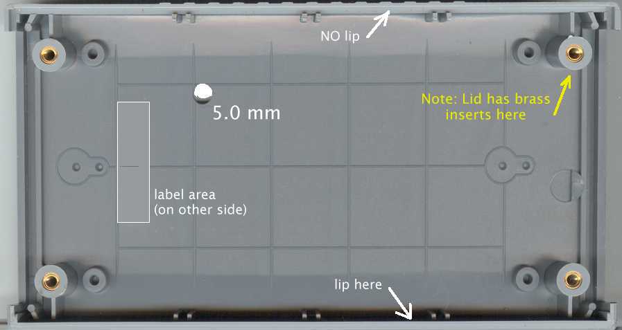
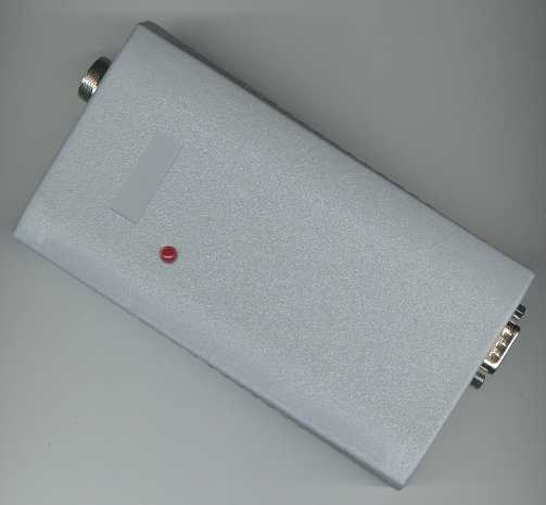
Drilling the Case for the LED
The image shows where a 5.0 mm hole must be drilled for the LED
Click on the image for an enlargement.
Note that the lid and base are "polarised" and must be
assembled with the small rectangular label area of both parts in the
same relative position (it's not a problem if you get it wrong though
as you can rotate the heatsink 180 degrees if necessary).
The 5 mm hole should edge up to the drill guide lines on the underside
of the lid.
The supplied LED on the WB PCB should now fit very well through the hole.
You may need to resolder the LED later to either raise or lower its height
which is best at 21 mm from the PCB's surface to domed tip of the LED.
No operations need be performed on the lower part of the case other than
removing the backing from the four rubber feet and attaching them with
the exposed adhesive. I place them as close to the four countersunk
holes and as close to the edge, but still on the horizontal area of the case, as possible.
Remember when assembling the top and bottom parts, that
the label area of each case half should be to the left, otherwise the
two halves won't mate properly.
Wiring the Unit's Connectors
Note: You should strip the 8-way flat cable in the kit into a 5-way cable with brown, red, orange,
yellow and green wires only. This will leave three wires organised as a 2-way and single wire (used later).
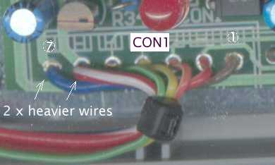
CON1 - to circular connector.
The 7-way CON1 wiring (on the PCB) is made up of the 5-way flat cable for the
rightmost pins 1 through 5 (the sensor's measurement and calibration components),
and two heavier wires of the same length for pins 6 and 7 (the heater).
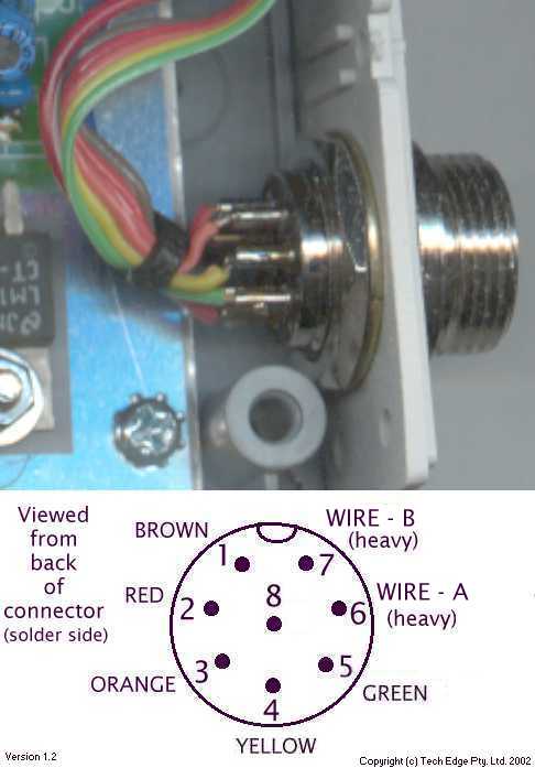
The circular connector is numbered (when looking at the solder side of the connector) in
anti-clockwise fashion starting at the raised locating hole found on the other side
(the numbers are embossed on the connector, so there should be no confusion).
The wiring between the PCB and the circular connector is straight through (ie. pin 1 to pin 1, etc)
and you should wire the circular connector first with the thin brown wire to pin 1,
then the next pin left is red to pin 2, etc.
Pin 8 in the centre of the connector is not used, nor wired to.
Note : the two heavy heater wires shown in the enlarged image are labelled as A and B
because we may supply different coloured wires in the kit.
Click on the image for an enlargement
A cable tie is used to pre-stress the 7 wires going to circular connector.
This operation minimises the possibility of metal fatigue of the wiring while
you are finishing construction and testing.
You could also have used heatshrink tubing over each pin to do the same job,
but we recommend you simply use one of the cable ties supplied, and place it
as shown in the image above. Do not over-stress the wires as this will
damage the solder joints as quickly as if you had left them alone.
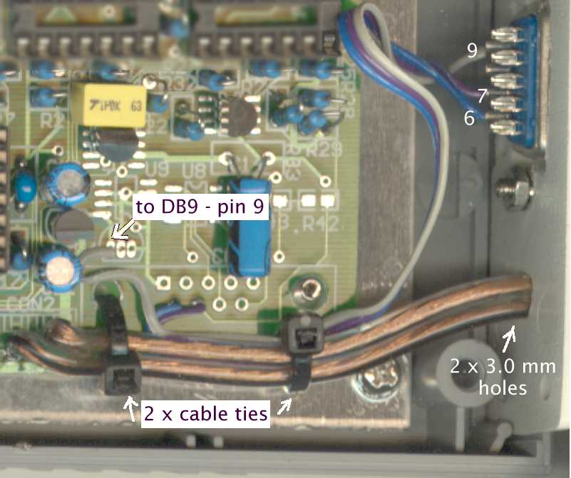
CON3 - WB output, Vbatt & GND to DB9.
Only three wires of the 7-way CON3 connector (on the PCB)
go to the DB9 in the end plate. The wire used is made up of the remaining three small
diameter flat wires stripped from the 8-way cable supplied in the kit
(the colours of these three wires may vary).
Connect the 2 wires (pins 6 and 7) one-to-one as shown here.
The third wire from pin 9 of the DB connector goes to the left hole of the
unused 78L05 regulator
pin 6 = GND
pin 7 = Vout Wideband output signal
pin 9 = battery voltage to 5300 display (see below)
CON2 Power Cable - figure eight to battery/GND.
A medium duty figure eight cable is eased through the holes in the right end-plate
and this is soldered direct to the PCB CON2 location.
The wire is not supplied in the kit and you should use medium duty
figure eight (ie. two core) cable of the type commonly used for desk lamps
and other mains powered devices that are not double insulated.
A suitable wire is classified (in metric) as 24/0.20 which is made up of 24 strands of
0.20 mm diameter and has an equivalent diameter of 0.75 mm (about 0.03").
Use a multi-strand wire with equivalent size of between 20 - 21 B & S gauge
(or 21 - 22 SWG ).
These gauge wires have a resistance of about 0.1 ohms per 3 metres (per 10 feet)
and a 4.5 m cable (~15 feet) will have a resistance of 0.3 ohms (total wire length is 9 m),
which is acceptable.
A thicker gauge [= smaller gauge number] may be used but as
the WB unit sinks 1.5 Amps max, anything heavier is overkill,
anything less quickly becomes susceptible to improper sensor heater operation.
Note the cable tie anchoring the figure 8 cable. It goes through the left DB9
CON3 hole (originally intended for the PCB mount DB9 connector).
The trace wire (the one with the thin opposite color band)
is assigned to be GND (although this is up to you).
You can also use a small piece of RED heatshrink
over the other end of this cable so you don't get confused (ie. red to battery,
AND, we're assuming a negative earth vehicle).
Other Items to Complete the Unit
The CX kit will require the PCB's two existing mounting holes to be enlarged
to 3.5 mm, and a further hole drilled (this is described here).
The bottom right mounting point (beside the DB9) will require the use of the clear
nylon M3 nut which is supplied threaded on the matching M3 bolt
(we do this so the nut is not lost when you open the kit!).
This nylon nut prevent shorting the Vout signal to heatsink and GND.
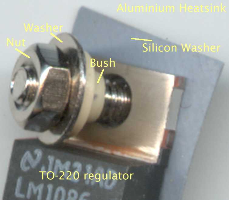
Insulating components for the TO-220 Heatsink - These parts are supplied
in the Oz DIY-WB parts kit and comprise a grey silicon impregnated square washer,
an M3 bolt, nut and flat washer, and a specially moulded white/beige plastic bush.
They are assembled, with everything sitting on the aluminium heatsink, as shown.
Note that you should tighten the TO-220 nut firmly, but not so tight that the insulating
bush will be damaged. Also ensure everything is aligned by doing up finger tight
and checking for any gaps.
At this point the PCB is probably attached to the heatsink and you have tested
everything according to the electronics assembly instructions.
All that remains is to bolt the heatsink and PCB assembly to the case with the four 6 mm
long M3 bolts (they will self tap into the ABS plastic case), making sure to use the
final four star washers to secure the bolts from vibration.
The lid should now go over the electronics and the LED should protrude about 1 or 2 mm
from the surface of the lid. If the lid is not oriented correctly with the base, simply
unscrew the four bolts holding the heatsink and rotate it 180° and bolt everything together.
Warnings and Vehicle Testing
Ensure you know which wire goes to the battery positive (the non-trace wire you placed a small
piece of RED heatshrink over) and wire it one last time to your bench setup before you wire it
into you vehicle. Resist the temptation to connect a female cigarette
lighter connector to the end of the power cable. We have found that many installations
have small voltage drops that can cause heater warm up problems when the vehicle is in use.
It is always better to connect as close to the battery as possible.
Use an in-line fuse (3-5 Amps) to protect the vehicle
should some fault develop in the WB unit or the cable to it, or even the NTK sensor.
Remember also that the sensor should :
be mounted no closer than about 15° to the horizontal
to ensure condensation doesn't drip onto the hot ceramic surface of the sensor
during the vehicle's warm up phase.
be mounted with the sensor at right angles to the exhaust gas
flow (ie. not "up the tail pipe") to ensure the diffusion chamber is not
prematurely clogged by carbon residue.
never be left in an exhaust gas stream unconnected from heater power
(the heater burns off carbon residue before it has time to contaminate the sensor).
You should use the sensor before any cat you may be using (this will typically
require a welded bung in your exhaust system), unless you're actually testing the efficiency of the
cat (the unit is not designed to measure AFR greater than 25:1 and free air has a close
to infinite AFR (although in some cities ...).
Feedback
We really do appreciate
your feedback on the content and any corrections necessary to this article.
Please help us to make these instructions as clear as possible by
giving me feedback about errors,
omissions, etc. Thank in advance.
